Showing posts with label software art. Show all posts

Sunday, March 31, 2013

[TUTORIAL] Visualizing Depth in Unity, part 2

    The joys of having a laptop capable of development, I'm seriously in love with my Ultrabook.  This isn't just me shilling for the company, I'm totally sold on this thing.  Apple did right by forcing people to figure out how to build smaller, lighter laptops that still pack serious development punch.  For reference, I'm currently working off of a Gigabyte U2442, would be nice to get something that has a Core i7 CPU, but this one's a Core i5 at 3.1 with a mobile Geforce 6xx, so I'm happy with it.  Made it easy for me to bang out this second depth sample from the comfort of a...actually I think it was a bar as opposed to a coffee shop...


The Technolust, i sorta haz it...

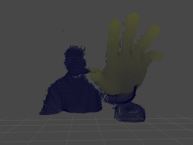
    I mentioned in my last post I'd been messing around with some other methods for visualizing depth from the Creative Camera, I took a few moments after GDC to decompress and finish this one up, it sorta builds off the last sample.  Instead of visualizing a texture, I'm using the depth to set attributes on some particles to get that point cloudy effect that everyone seems to know and love.  This one's a bit more complex, mainly because I added a few parameters to tweak the visualization, but if you've got some Unity under your belt, none of this will be that tricky, and in fact, you'll probably see pretty quickly how setting particle data is very similar to setting pixel data.  I should also note that the technique presented here could apply to any sort of 3d camera, pretty much if you can get an array of depth values from your input device, you can make this work.  So here's what we're trying to accomplish when all's said and coded:

    Since this is a Unity project, we'll need to set up a scene first.  All that's required for this is a particle system, which you can create from the GameObject menu (GameObject > Create Other > Particle System).  Set the particle system's transforms (translate and rotate) to 0,0,0 and uncheck all the options except for Renderer.  Next, set the Main Camera's transform to 160,120,-240, and our scene is ready to go.  That all in place, we can get to coding.  We'll only need a single behavior for this test, which we'll put on the particle system.  I called mine PDepth, but you'll call it Delicious (or whatever else suits your fancy)!  First, let's set up our particle grid and visualization controls:

//We'll use these to control our particle system
public float MaxPointSize;
public int XRes, YRes;

private ParticleSystem.Particle[] points;
private int mXStep, mYStep;

  • MaxPointSize: This controls the size of our particles
  • XRes, YRes: These control the number of particles in our grid
  • points: This container holds our individual particle objects
  • mXStep, mYStep: These control the spacing between particles (this is calculated, not set manually)

    With those in place, we can populate our particle grid and get some stuff on screen.  Here's what our initial Start() and Update() methods should look like:

void Start()
{
    points = new ParticleSystem.Particle[XRes*YRes];
    mXStep = 320/XRes;
    mYStep = 240/YRes;

    int pid=0;
    for(int y=0;y<240;y+=mYStep)
    {
        for(int x=0;x<320;x+=mXStep)
        {
            points[pid].position = new Vector3(x,y,0);
            points[pid].color = Color.white;
            points[pid].size = MaxPointSize;
            ++pid;
        }
    }
}

void Update()
{
    particleSystem.SetParticles(points, points.Length);
}

    If you're wondering where the values 320 and 240 came from, we're making some assumptions about the size of our depth map to set the initial bounds.  Once we add in the actual depth query, we'll fix that and not have to rely on hardcodes.  Otherwise, if all went according to plan, we should have a pretty grid of white particles.  Be sure to set some values for XRes, YRes, and MaxPointSize in the Inspector!  For this example, I've used the following settings:
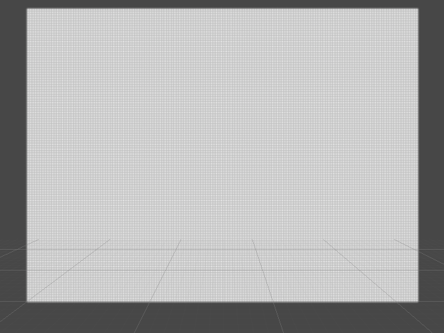
  • XRes: 160
  • YRes: 120
  • MaxPointSize: 5

    As I mentioned earlier, this procedure actually isn't too much different from the previous sample, in that we're building a block of data from the depth map then loading it into a container object, just in this case we're using an array of ParticleSystem.Particle objects instead of a Color array, and we're calling SetParticles() instead of SetPixels().  That in mind, you've probably already started figuring out how to integrate the code and concepts from the previous tutorial into this project, so let's go ahead and plow forward.  First, well need to add a few more members to our behaviour:

public float MaxPointSize;
public int XRes, YRes;
public float MaxSceneDepth, MaxWorldDepth;

private PXCUPipeline mSession;
private short[] mDepthBuffer;
private int[] mDepthSize;
private ParticleSystem.Particle[] points;
private int mXStep, mYStep;

  • MaxSceneDepth: The maximum Z-amount for particle positions
  • MaxWorldDepth: The maximum distance from the camera to search for depth points
  • mDepthBuffer: Intermediate container for depth values from the camera
  • mDepthSize: Depth map dimensions queried from the camera. We'll replace our hardcoded 320,240 with this

    The only major additions we need to make to our Start() method involve spinning up the camera and using some of that information to properly set up our particle system.  Our new Start() looks like this:

void Start()
{
    mDepthSize = new int[2];
    mSession = new PXCUPipeline();
    mSession.Init(PXCUPipeline.Mode.DEPTH_QVGA);
    mSession.QueryDepthMapSize(mDepthSize);
    mDepthBuffer = new short[mDepthSize[0]*mDepthSize[1]];

    points = new ParticleSystem.Particle[XRes*YRes];
    mXStep = mDepthSize[0]/XRes;
    mYStep = mDepthSize[1]/YRes;

    int pid=0;
    for(int y=0;y<mDepthSize[1];y+=mYStep)
    {
        for(int x=0;x<mDepthSize[0];x+=mXStep)
        {
            points[pid].position = new Vector3(x,y,0);
            points[pid].color = Color.white;
            points[pid].size = MaxPointSize;
            ++pid;
        }
    }
}

    The bulk of the changes are going to be in the Update() method.  The big difference between working with a particle cloud and a texture as in the previous example is that we need to know the x and y positions for each particle, thus the nested loops as opposed to a single loop for pixel data.  This makes the code a bit more verbose, but not a ton more difficult to grok, so let's take a stab at building a new Update() method:

void Update()
{
    if(mSession.AcquireFrame(false))
    {
        mSession.QueryDepthMap(mDepthBuffer);
        int pid=0;
        for(int dy=0;dy<mDepthSize[1];dy+=mYStep)
        {
            for(int dx=0;dx<mDepthSize[0];dx+=mXStep)
            {
                int didx = dy*mDepthSize[0]+dx;

                if((int)mDepthBuffer[didx]>=32000)
                {
                    points[pid].position = new Vector3(dx,mDepthSize[1]-dy,0);
                    points[pid].size = 0.1f;
                }
                else
                {
                    points[pid].position = new Vector3(dx, mDepthSize[1]-dy, lmap((float)mDepthBuffer[didx],0,MaxWorldDepth,0,MaxSceneDepth));
                    float cv = 1.0f-lmap((float)mDepthBuffer[didx],0,MaxWorldDepth,0.15f,1.0f);
                    points[pid].color = new Color(cv, cv, 0.15f);
                    points[pid].size = MaxPointSize;
                }
                ++pid;
            }
        }
        mSession.ReleaseFrame();
    }

    particleSystem.SetParticles(points, points.Length);
}

    So like I said, a bit more verbose, but hopefully not terribly difficult to understand.  A few things to be aware of:

int didx = dy*mDepthSize[0]+dx;

    We use the variable didx as an index into the depth buffer.  The reason we do this is because our particles don't correspond 1:1 to values in the depth buffer, so we use each particle's x and y position to do the depth buffer lookup.  In the next example, we'll take a look at how we can actually have a 1:1 depth buffer to particle setup using generic types.

if((int)mDepthBuffer[didx]>=32000)
{
...
}
else
{
...
}

    Here, the reason we test against a depth value of 32000 is because this is what the Perceptual Computing SDK uses as the error term.  So if the SDK can't resolve a depth value for a given pixel, it sends back 32000 or more.  In this case, if we find an error term, we make the particle really small, but in the next example, we'll look at how we can skip that particle altogether if we have an error value.  Finally, remember we need to implement some sort of range remapping function, I call mine lmap as a homage to Cinder's remap, but you can call it whatever, again, it's basically just:

float lmap(float v, float mn0, float mx0, float mn1, float mx1)
{
    return mn1+(v-mn0)*(mx1-mn1)/(mx0-mn0);
}

    So that's that, in the next sample, we'll look at some different ways to map the depth buffer to a particle cloud and use the PerC SDK's UV mapping feature to add some color from the RGB stream to the particles.  Until then, email me, follow me on Twitter, find me on facebook, or otherwise feel free to stalk me socially however you prefer.  Cheers!

What can i say, i love OpenNI...

Wednesday, March 27, 2013

[TUTORIAL] Depth maps and Ultrabooks

    Went to a really great hack-a-thon this past weekend at the Sacramento Hacker Lab to help coach some folks through working with the Perceptual Computing SDK and got to see some really cool work being done, everything from a next-generation theremin to a telepresence bot, all powered by the Creative 3D Camera and Perceptual Computing SDK.  Does me good to actually get out into the community and see people just dive right in and start building stuff.  Compound that with the GDC Dev Day that personally I think went amazingly well (standing room only at one point!) and it's been a good GDC for Perceptual Computing so far.  But now comes the really hard part, which is that PerC needs to not become a victim of its own success.  As the technology gets into more hands, now it becomes about not burning through goodwill by breaking features, being uncommunicative, or not keeping up with the ecosystem.  But I digress...

    Wanted to share a little Unity tip I got asked about a few times during the hack-a-thon, and that's how to visualize the depth map.  The SDK ships with a sample for visualizing the label map, and visualizing the color map is a fairly trivial change, but visualizing the depth map requires a little bit of doing.  It's actually pretty trivial from a working standpoint, so let's take a look at what's required.

    To get a depth map into a usable Texture2D, the basic flow is:
  • Grab the depth buffer into a short array
  • Walk the array of depth values and and remap them into 0-1 range
  • Store the remapped value in a Color array
  • Load the Color array into a Texture2D
    If that seems really simple, fear not, it actually is, so let's take a look at some code and see how we accomplish this.  Here's a really simple Unity behavior that populates the texture object from the depth map.  I'll leave assigning the texture as an exercise to the readers:

using UnityEngine;
using System.Collections;

public class Test : MonoBehaviour
{
    private PXCUPipeline mSession;
    private int[] mDepthSize;
    private short[] mDepthBuffer;
    private int mSize;

    private Texture2D mDepthMap;
    private Color[] mDepthPixels;

    void Start()
    {
        mDepthSize = new int[2];
        mSession = new PXCUPipeline();
        mSession.Init(PXCUPipeline.Mode.DEPTH_QVGA);
        mSession.QueryDepthMapSize(mDepthSize);
        mSize = mDepthSize[0]*mDepthSize[1];

        mDepthMap = new Texture2D(mDepthSize[0], mDepthSize[1], TextureFormat.ARGB32, false);
        mDepthBuffer = new short[mSize];
        mDepthPixels = new Color[mSize];
        for(int i=0;i<mSize;++i)
        {
            mDepthPixels[i] = Color.black;
        }
    }

    void Update()
    {
        if(mSession.AcquireFrame(false))
        {
            mSession.QueryDepthMap(mDepthBuffer);
            for(int i=0;i<mSize;++i)
            {
                float v = 1.0f-lmap((float)mDepthBuffer[i],0,1800.f,0,1.f);
                mDepthPixels[i] = new Color(v,v,v);
                mDepthMap.SetPixels(mDepthPixels);
                mDepthMap.Apply();
            }
            mSession.ReleaseFrame();
        }
    }

    float lmap(float val, float min0, float max0, float min1, float max1)
    {
        return min1 + (val-min0)*(max1-min1)/(max0-min0);
    }
}

    So like i said, fairly simple, albeit verbose technique, but should be fairly easy to wrap it up into a simple function for quick future use.  This same technique can also be used to visualize the IR map with some very minor tweaks.  I've actually been doing alot of stupid depth map tricks the last few days.  I'm at GDC all this week so I'm not sure how much dev time I'll get to be able to polish a few more of these up but maybe the weekend'll afford me some cycles if i'm not in full on crash out recovery mode...

Wednesday, January 30, 2013

[CODE] simple bullet physics debug draw for Cinder


    Not horribly hard to figure out but if you feel like saving yourself some code time or just looking for a quick jumping off point, here you go.  You can also grab the whole project from github.  If this looks like a straight port of bullet's GLDebugDrawer, it pretty much is.

.h
#include "cinder/app/AppBasic.h"
#include "cinder/gl/gl.h"
#include "cinder/Text.h"
#include "btBulletDynamicsCommon.h"
#include "LinearMath/btIDebugDraw.h"

using namespace ci;
using namespace ci::app;
using namespace std;

class CibtDebugDraw : public btIDebugDraw
{
    int m_debugMode;
public:
    CibtDebugDraw();
    virtual ~CibtDebugDraw();
    virtual void drawLine(const btVector3& from, const btVector3& to, const btVector3& fromColor, const btVector3& toColor);
    virtual void drawLine(const btVector3& from, const btVector3& to, const btVector3& color);
    virtual void drawSphere(const btVector3& p, btScalar radius, const btVector3& color);
    virtual void drawBox(const btVector3& bbMin, const btVector3& bbMax, const btVector3& color);
    virtual void drawContactPoint(const btVector3& PointOnB, const btVector3& normalOnB, btScalar distance, int lifeTime, const btVector3& color);
    virtual void reportErrorWarning(const char* warningString);
    virtual void draw3dText(const btVector3& location, const char* textString);
    virtual void setDebugMode(int debugMode);
    virtual int getDebugMode() const;
};

.cpp
CibtDebugDraw::CibtDebugDraw() : m_debugMode(0)
{
}

CibtDebugDraw::~CibtDebugDraw()
{
}

void CibtDebugDraw::drawLine(const btVector3& from, const btVector3& to, const btVector3& fromColor, const btVector3& toColor)
{
    gl::begin(GL_LINES);
    gl::color(Color(fromColor.getX(), fromColor.getY(),
        fromColor.getZ()));
    gl::vertex(from.getX(),from.getY(),from.getZ());
    gl::color(Color(toColor.getX(), toColor.getY(), toColor.getZ()));
    gl::vertex(to.getX(),to.getY(),to.getZ());
    gl::end();
}

void CibtDebugDraw::drawLine(const btVector3& from, const btVector3& to, const btVector3& color)
{
    drawLine(from,to,color,color);
}

void CibtDebugDraw::drawSphere(const btVector3& p, btScalar radius, const btVector3& color)
{
    gl::color(Color(color.getX(), color.getY(), color.getZ()));
    gl::drawSphere(Vec3f(p.getX(),p.getY(),p.getZ()), radius);
}

void CibtDebugDraw::drawBox(const btVector3& bbMin, const btVector3& bbMax, const btVector3& color)
{
    gl::color(Color(color.getX(), color.getY(), color.getZ()));
    gl::drawStrokedCube(AxisAlignedBox3f(
        Vec3f(bbMin.getX(),bbMin.getY(),bbMin.getZ()),
        Vec3f(bbMax.getX(),bbMax.getY(),bbMax.getZ())));
}

void CibtDebugDraw::drawContactPoint(const btVector3& PointOnB, const btVector3& normalOnB, btScalar distance, int lifeTime, const btVector3& color)
{
    Vec3f from(PointOnB.getX(), PointOnB.getY(), PointOnB.getZ());
    Vec3f to(normalOnB.getX(), normalOnB.getY(), normalOnB.getZ());
    to = from+to*1;

    gl::color(Color(color.getX(),color.getY(),color.getZ()));
    gl::begin(GL_LINES);
    gl::vertex(from);
    gl::vertex(to);
    gl::end();
}

void CibtDebugDraw::reportErrorWarning(const char* warningString)
{
    console() << warningString << std::endl;
}

void CibtDebugDraw::draw3dText(const btVector3& location, const char* textString)
{
    TextLayout textDraw;
    textDraw.clear(ColorA(0,0,0,0));
    textDraw.setColor(Color(1,1,1));
    textDraw.setFont(Font("Arial", 16));
    textDraw.addCenteredLine(textString);
    gl::draw(gl::Texture(textDraw.render()),
        Vec2f(location.getX(),location.getY()));
}

void CibtDebugDraw::setDebugMode(int debugMode)
{
    m_debugMode = debugMode;
}

int CibtDebugDraw::getDebugMode() const
{
    return m_debugMode;
}

Here's a quick shot of the debug drawer in action with a single body:

Saturday, December 29, 2012

C4CNC101 - Section 1: Intro To Functions

DISCLAIMER:
(1) If you are already familiar with functions, variables, types, otherwise coding basics, C4CNC101 is not for you.  I'd recommend taking a look at something like The Nature Of Code if you're interested in getting up and running with processing.
(2) A familiarity with digital art in general, including coordinate systems, pixels, etc will be extremely helpful.  If you've ever used Photoshop, Illustrator, or any other digital art program, 2d or 3d, you should be good to go.
(3) If you're a programmer, you'll probably find tons of inconsistencies or things i'm glossing over.  My goal here is not to teach programming, it's more to get people who want to get into using code as a tool to create or augment the creation of art up and running, enough to give them the foundation knowledge to research deeper if they so choose.  I've done alot of thinking about this and I believe the information as I've presented it is true in spirit and in the scope of processing.

header
    Ok, so hopefully by now you've downloaded and installed processing, signed up for an OpenProcessing account, and joined the C4CNC Classroom on OpenProcessing.  The first step is really the only requirement, but i do recommend at least peeking around OpenProcessing to get an idea of what's possible.  I'll warn you in advance that if you're just starting out, it can be pretty easy to get overwhelmed by the breadth and depth of content therein, but fear not!  Hopefully by the time we're through these first five lessons, you'll know enough to read through some of the sketches and even build your own sketches based off of them.  As I mentioned in the last post, if you come across any sketches or effects you'd like to remix, breakdown, or dive into deeper, let me know and I'll work something out for a future set of tutorials.  Alright, so let's begin!

    First, let's conceptualize a computer program as nothing more than a set of commands or instructions that processes information and produces results based on the specifics of the information and the commands.  While that's a bit of an oversimplification, on some level this holds true for any program, from the small visualization sketches we'll be writing here, all the way up to full on operating systems like Windows or Linux.  We call these instructions functions and we call the information data.  So let's write our first program.  Open processing and type the following function:

ellipse(50, 50, 50, 50);

    Once that's in place, press the Run button (it looks like a 'Play' button) in the upper left hand corner.  Alternately, you can check out the sketch on OpenProcessing(1-1: Basic Functions), although I highly recommend you follow along by typing the code yourself to get the most out of these lessons.  Either way, you should see something like the following:

Step1_0

CODERSPEAK: When we issue a command in a program, we say we are calling the function or making a function call, and when we provide data to a function, we say we are passing an argument (or arguments).  So when we issue a command and give it some information, we are calling a function with arguments.

    This may not look like much, but it's actually a valid processing sketch, so congrats.  In some languages, Python for example, a single function like this could also comprise a valid and complete program, so not bad for a first step!  Sure, it's not very exciting and doesn't do much, but we'll get there.

    Now, let's take a moment and break down our function call.  For our intents and purposes, every function call will be a name followed by a set of parentheses.  If we're passing arguments to the function, they'll be between the parentheses, separated by commas.  And finally, we end our function call with a semicolon, so processing knows to move on to the next function.  Thus, the skeleton for any function call is:

functionName(argument1, argument2, argument3, etc);

    Recall that we started out by defining a program as a set of commands(functions) that processes information(data) to produce a result.  Arguments are how we provide the data to a function.  In cases where we're passing multiple arguments, each argument is used by the function to perform a specific task along the way to producing the final result.  So in the case of our first sketch here, as the programmer we're telling processing to:

Draw an ellipse with a position of 50 pixels along the x-axis and 50 pixels along the y-axis, and a size of 50 pixels along the x-axis and 50 pixels along the y-axis.

    Most, if not all, publicly available coding tools and environments have references that describe (some in more detail than others) what each argument does.  For example, take a look at the reference page for the ellipse() function, which not only details the arguments, but also provides some useful tips on calling ellipse().

    Alright, so let's practice a bit by adding a few more functions.  Add another function before the ellipse() call, so your sketch contains the following function calls.  Note that we're changing some of the arguments to the ellipse() call, and you should feel free to change any of the arguments to any of the functions.  Experimentation is a key to learning!

size(400, 400);
ellipse(200, 200, 50, 50);

    As you can probably tell from the result, the size() function sets the size in pixels of our sketch's window.  Even though both functions take a different number of arguments and produce markedly different results, you can see that they both follow the same skeleton we outlined above, i.e.:

functionName(argument1, argument2, argument3, etc);

    Before we get a little more advanced, let's add a few more basic processing functions, again for practice, and also to see how we can affect what we're drawing on-screen so we can start getting an idea of the kind of drawing functionality that processing makes available to our sketches.  We're going to add three more function calls in-between our size() call and our ellipse() call: background(), stroke(), and fill().  Type these functions in as presented below:

size(400, 400);
background(0, 0, 0);
stroke(255, 255, 255);
fill(0, 128, 255);
ellipse(200, 200, 100, 100);

    As the saying goes, the more things change, the more things stay the same.  As we add functions, we see the results compound and the output become more complex, but in the end, all functions are called in the same manner using the same syntax.  Feeling comfortable typing in functions?  Then give the following exercises a try and see what you come up with.  Questions?  Please post them in the comments!

footer
EXERCISE 1: Draw 5 different ellipses with different radii and in different locations.  Be sure to check out the Processing Language Reference for ellipse() for more details on how the ellipse() function works.  Try changing some of the arguments to the other functions as well!
Exercise 1-1

EXERCISE 2: Take a look at the Language Reference for background(), stroke(), and fill().  Now, take the previous exercise and change the stroke and fill color for each ellipse. While you're at it, change the background color to something a bit friendlier than black, it's getting a bit gloomy in here...
Exercise 1-2

CODERSPEAK: You might be wondering how processing knows what to do when we call any of the functions presented here.  Well, most, if not all programming languages and environments come with a set of pre-existing functions and data that we use to build up our programs initially, which you'll often hear referred to as built-ins or library functions.  When writing programs, you'll use a combination of both built-in functions and data, as well as functions and data you define yourself.  We'll discuss this process in the next couple lessons.


PREVIOUS ARTICLES
Foreword
Project Preview